
the VORTEX WORLD
the repulsin
|
||
|
 |
|
| Imagine that we could control that force .... | ||
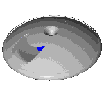
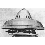
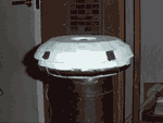
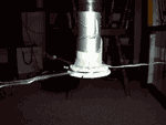
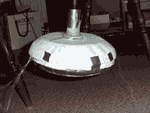
| Among Viktor Schaubergers machines there is no one like the Repulsin or the flying saucer that has created such myths and stories. The basic designs are from the mid thirties when he tried to finish the Climator. Often mysterious material acting as catalysts are used in the devices. Different light and sound phenomena are also reported from people that claim that they had been eye witnesses to these flying devices. A most peculiar thing is that they seem to be very difficult to control, as they have a habit of smashing into the ceiling, and after that, being irreparable. Viktor himself claimed that powerful diamagnetic forces were responsible for the enormous effect. However, in the literature and in Viktor's own notebooks there is no evidence, if and if so how these devices worked. The question is, are all these rumours true ? Do these devices really work ? Well, what we can see from the few pictures that exist is that there seems to be some kind of turbine, shaped as a double flat membrane with concentric rills on it. If you compare to the wave pattern you get when you throw a stone into a small pond you will comprehend better what I mean. However, the wave pattern on the upper membrane had a small difference in the phase compared to the lower membrane. On the edge rim, turbine vanes are mounted, probably acting as a source of power for both self rotation and even for the generation of power. The double membrane was probably co-rotating as four bolts that fix them together, can be observed. In the pictures we can also see that there is some kind of body, a bowl shaped plate that is bend over the membrane whose outlet can be found inside the rim foil. Together, the rim foil (the metal band around the lower rim) and the outlet form a Venturi "tube". An air intake can be seen on the top of the device. Unfortunately, one important component is missing on the top. This component should "pre-form" the air so it starts to twist before it enters the double membrane. This component had a similar shape as a sea shell. Viktor said that this device was never built as it is very difficult to produce a thing with such a complex geometry. In the book Living Water (by Olof Alexandersson) a colloid solution of very fine grained quartz crystal and water is mentioned as a catalyst for the process. So, if we start to think for a while. Let's say that this device really worked, it really did take off! How would it work ? Consider what probably happens in the machine: - The air is sucked through the intake where it is pre-formed into a vortice containing vortices within vortices shaped as long threads rotating around their axis.In my opinion the double membrane was not co-rotating. If they where not counter rotating, one of the was fixed, probably the upper membrane and the lower rotating on the driving axis. A description on what happens is given on the wind mill page. - Briefly the air threads start to spin faster and faster around their axis driven by the difference in speed between the membranes. As the air reaches longer out on the membrane, the peripherical speed increases along with the radius and so does the angular speed of the air threads. - During the passage between the double membrane the air has to pass cavities where the volume sometimes is bigger and sometimes is smaller due to the difference in phase between the upper and the lower membrane. When the air passes a narrow cavity it gets extra energy input and when it passes a larger cavity it is allowed to expand. - The "air threads" are twisted along their axis in a smaller and smaller radius leading to an increase of the angular speed. As the air reaches further out, closer to the rim, the threads start to bend due to the increasing peripherical speed. When the air passes the different cavities it starts to pulsate in a rhythm that is depending on the angular speed of the disc. Huge forces are generated when all these degrees of freedom are harmonised into a symphony. However, it is not necessary to use unknown theories as the diamagnetic forces to explain how the powerful lift is generated. Of course this can be the explanation, the future will show us if this is the case. As for the colloid solution of fine grained quartz and water, one can imagine that huge amounts of piezo electricity is produced between the membranes, where the pulsating and twisting air containing small amounts of the solution is passing. At a certain rotation speed we have reached the level where we have "harmony" and the air is "self pulsating" and generating electricity that "pumps" up the energy level. What actually happens in this process in certainly unknown! But, high levels of static electricity have been reported in similar devices connected to the ZPE-area. ZPE stands for zero point energy or vacuum energy which is the idea of an unknown field of energy existing in vacuum. Read more about this phenomena! In several proposals of propulsion devices, for flying saucers high electric energy levels are also used. As an example we have David Hamels flying disk. You can read about it here. It could be that the diamagnetism that Viktor Schauberger mentioned, is the same phenomena or physical principle that is proposed in these propulsion devices. In Viktor's lessons he always talked about two important things: "You shall always remember two things. First, remember how the rivers are meandering. Second, remember the electrophorus (or Kelvin's thunderstorm ) experiments!" As I mentioned before there is one (at least ) more explanation on why Viktor Schaubergers machine took off with such power. It might be explained by "normal" aerodynamics and a phenomena named the Coanda effect'. Very brief the Coanda effect is the phenomena when a flowing media tends to "stick" to a curved surface, You can read a biography of Henri Coanda here . If we take a closer look on the bowl shaped plate, we realise that it is a circular wing. When the air is rushing out inside the foil or the metal band that can be seen on the lower rim of the device it creates a sub pressure just over the foil. The surrounding air is sucked inside the foil and with the air from the membranes. This generates a sub pressure over the device and the device is "hanging" in it. You could say that it is an inverted hovercraft. But instead of creating a pressure under the craft You create a sub pressure over it. Basically it is the same, it is only a matter of pressure differences. The sub pressure is modest but as we have a large area we also get a huge lifting force. There is one more way to create the sub pressure over the craft. You can let the air blow out on the top instead. When the twisted air follows the Coanda surface it sweeps down the surrounding air and we get the sub pressure this way. If You want to read more about the Coanda effect follow this link . On this page You can read a lot about different applications and a very interesting new type of fan, the Jet Fan. |
||
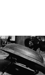
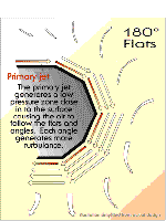
| The principle of the "flats and angles" (type 1) is demonstrated in picture 1, where I have built a small (250 mm diameter, 80 mm high) prototype of the Jet Fan type (type1). I have also "rebuilt" my vacuum cleaner so it is blowing instead (my wife demanded a new one
). The air blows out through a special nozzle so it forms a "disk" of blowing air. Picture 2: When the nozzle with the "air disk" is placed close to the top, we can simulate what is happening on type 1. As You can see in the picture, the silk threads follow the air flow shoving the path. Picture 3: Oh Yes, It works ! |
||
| The Malmögroup will continue their work during 1998 with further testing of these ideas. We proposed a model of the membrane turbine and will continue to shape the moulds so we can multiply the membranes. A section of the body will also be designed as a test rig where it will be possible to test different profiles of the body and different types of nozzles and other things related to the device. We will also present the results on this page, please continue to check the site. I will write in the "what's new section" when there is more info. | ||
 |
 |
|---|
| Repulsin type B, inner part of air inlet removed |
 |
|---|
 |
|---|
| Picture 1 |
 |
| Picture 2 |
 |
| Picture 3 |
the Malmö group l Viktor Shauberger l water treatment l the repulsin l energy production l more links